Best Of
Thank You for a Wonderful Year in the Seequent Community
As we head into the holiday season, I wanted to take a moment to acknowledge the collaboration, curiosity, and knowledge-sharing that shaped the Seequent Community this year.
Thank you to everyone who contributed, shared insights, supported a peer, or simply checked in from time to time. Looking forward to everything we’ll continue building together in 2026.
Wishing you all a restful break and a smooth start to the new year!
💥 Exciting Updates in Visible Geology!
We’re thrilled to announce some powerful new features designed to make your geological modelling experience more intuitive, efficient, and visually clear.
👀 Plus, Google account login for Visible Geology is coming soon! Keep an eye out for more information.
Here’s what’s new:
👉🏼 Edit custom topography
No more starting from scratch! You can now reshape, refine, and adjust existing custom topographies directly within Visible Geology.
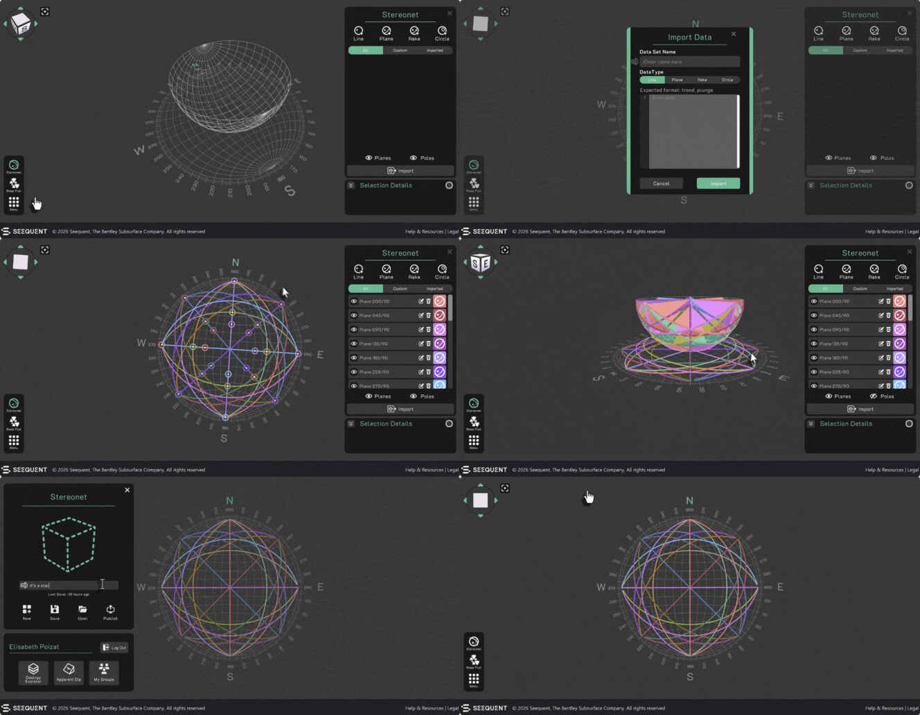
👉🏼 Import stereonet data
Save time by instantly importing planar or linear data from spreadsheets or text files - no more manual entry!
👉🏼 Create topography from contour lines
Gain full control over your topographies by using contour lines and elevation data to create precise models.
👉🏼 Lithology legend display
Easily view the lithologies in your models with a new dynamic legend. As you model, the legend updates!
👉🏼 Stereonet rose plot
Generate, view and export intuitive rose plots from your existing project data to visualise structural patterns.
👉🏼 Stereonet toggle for poles and planes
The new toggle feature lets you show or hide poles and planes in the Stereonet view, keeping your diagrams clean and focused.
👉🏼 Set colours for assignments
It's now easier to differentiate and organise multiple assignments visually with custom colours.
Shown above: Importing stereonet data
We’ve also resolved some pesky bugs to make your experience smoother, including:
- Plunge fold behaviour bug fixed
- Unity upgrade implemented
- Stereonet auto-naming vs parameter confusion resolved
- Zoom speed adjusted for better control
- Decals no longer cross models
Ready to explore these improvements? Visit www.visiblegeology.com, log in to Visible Geology and experience the updates today!
Re: Creating a classic strike-dip symbol in Plan View Layout
If you already have a fault line:
- In the Structural Modeling Foder, select New Structural Data Point ( https://help.seequent.com/Geo/2024.1/en-GB/Content/structural-data/structural-data.htm#new-structural-data )
2. In the Plane View, navigate to the Structural Data folder, add a new Structural Data item, and configure it as shown in the image below.
I hope this information is helpful for your work!😊
Seequent Learning at EGU 2025 in Vienna
To stay abreast of current developments in geoscience, Seequent Learning geoscientists often attend international conferences and workshops. I attended the European Geosciences Union annual meeting in Vienna in April and participated in session on geoscience for the energy transition and energy storage.
Having subject matter experts go to conferences and workshops is one of the ways that Seequent helps ensure that its training content is up-to-date with the latest industry and academic knowledge and trends.
🚀 What's new in Visible Geology - May 2025
We are excited to announce that several enhancements have been made to Visible Geology to make your modelling even smoother!
Try them for yourself at www.visiblegeology.com, and let us know what you think in the comments below 👇️
- You can now bring more colour to your geological models by using the colour picker for dikes, plutons, and faults;
- When creating cores, you can now enter trend and plunge values in a data field and name your creation instead of using a default name;
- We've added directions on the grid so you can better locate yourself when using Visible Geology;
- Across Visible Geology, we've made efforts to match worldwide notation standards, displaying strike, rake, and trend with three digits;
- Lastly, in the Stereonet tool, you can now cancel your action upon creating a stereonet projection, avoiding the need to save and then delete it.
Plus, we've addressed some pesky issues you may have encountered:
- Contour lines have been enhanced for better visibility on topography and we've removed the straight lines that were incorrectly linking topography lines;
- Sections rendering will now appear correctly on complex geological models, regardless of their azimuth.
As always, we appreciate the support and feedback from the Visible Geology community!
New to GeoStudio? Get Started with the GeoStudio 2D Course from Seequent Learning Center!
Whether you're new to geotechnical modeling or just getting started with GeoStudio, this self-paced, beginner-friendly course is the perfect entry point. Offered through the Seequent Learning Center, the GeoStudio 2D course provides a hands-on introduction to the fundamentals of setting up and reviewing a 2D analysis in GeoStudio.
Here is what you will gain by the end of this course!
- Create or open GeoStudio project files
- Navigate the user interface with confidence
- Add and modify geometries and analyses
- Import geometries from past projects or DXF/DWG files
- Refine the mesh and add surface layers
- Use visualization and graphing tools for result interpretation
- Adjust print settings and work with custom printing templates
Ready to begin your learning journey! Enroll Now! ✅
Re: Edit Category Selections in Point Data
Perfect, thank you very much! This is a very good work around - all my data is safe and restored now.
One little comment: What I found a bit unclear, is, whether or not I should base my newly created category column on my orginial editable category column. I would like to precise that you must choose "<None>" for the source column, otherwise it wount work.
Thanks a lot!
Samuel
Re: Implicitly Selecting a Mesh Partition After Clipping
What are you going to use the individual parts for later? Are you using them as individual domains or inputs into another model?
There might be a way to set it up so that each shear is broken by one of the objects that you are using to split them in your second to last operation.
Ex if the shears are vertical vein surfaces and they are cut by another vein that is more horizontal. Then you could use that surface as a "fault" to split the vein volumes into fault blocks. Giving them unique identifiers to be used later.
Kind of like this, where the teal vein surfaces needs to be unique above and below the red vein surface. Then the red vein HW/FW or references surface (green) could be used as a fault.
I might be going in the complete wrong direction here though 😎
Re: Check out our Seequent Learning Centre!
One thing I wanted to add to this, is that you can set your preferred language, by clicking on your initials at top right of page, which takes you to your profile page:
Once there, you can select your preferred language, as highlighted above. Once you do this, the Catalogue page will default to show the available courses in your preferred language.
Check out our Seequent Learning Centre!
Hello, I'm Darren Andrews, one of Seequent's instructional designers. In recent years, we have transformed our online training experience with the creation of the Seequent Learning Centre! It is now the place to access all of our e-learning courses and other learning material. Clicking on this link will take you there:
.
Today I wanted to give you a very quick tour: after you log in, the Home and My Learning pages show all the courses and learning paths you are currently enrolled in:
The Catalogue page lists all the available courses, learning paths and live sessions that we offer:
The Seequent Learning Centre contains a wide variety of content, so we recommend using the Category filter to more easily find the content you are looking for. Our content is categorised by both product and language:
Within the catalogue, hovering over a course tile with your mouse cursor will provide you with buttons that you can click on to enrol in and start that course:
Finally, Seequent Learning Centre also hosts plenty of other types of technical content, like tutorials, course guides, how-to guides and sample data! All of this is available within the Resources page:
This Resources page is the first place to look if you cannot find a course or learning path for the product or workflow you want to learn.
If you have any questions about the Seequent Learning Centre or any of our training content, please contact us here, or contact our support team, who are always available to help!


