Is therea way in Leapfrog to represent lithologies intersecting a pit wall? I done see a way to Eval


Answers
-
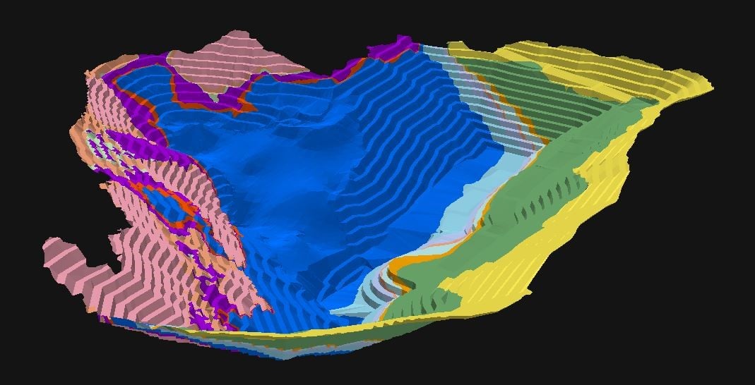
Any way to evaluate a Geologic model onto a "mesh"?? Pit wall like in this example purported to be a 3d dxf.0
-
Just went through a detailed workflow in the old forum which is still very much alive, I assume Seequent will work out how to merge them eventually.
https://forum.leapfrog3d.com/t/export-sections-maps-parallel-to-terrain-surface/3691
0 -
Hey, I see this an older post, but I'm now trying to do a similar thing and running into issues constantly. I'm trying to make a geological model (and ultimately a cross-section) from field-mapping data along cliff faces, so topography and 'bird's eye view' strategies are not as practical. The post you linked (export-sections-maps-parallel to-terrain-surface) is no longer active. Do you have any other suggestions?
0 -
Hi Emily,
I think the workflow post from the old forum is gone forever as this community discussion page had superseded it.
However, I can suggest one possible workflow for what I think you want to do.
If you have wireframes (meshes, surfaces) for your cliff faces then import them into Leapfrog.
If you don't have a 3D mesh of your cliff face then you will have to create one. I should be as close to true scale and location (northing, easting and RL) as possible.
Next step is to create a "New Cross Section From Image", located under the Sections, Plans and Contours folder. (help link here Maps and Images (seequent.com)). When you chose your image (your mapped section) you will get a dialogue box to geo-reference it. You can put in exact X, Y and Z coordinates (which should match the coordinate space your mesh is in, i.e. same scale), or click on the small square, circle and diamond buttons in turn and select a point on your mesh where those points on your image represent. Rotate the mesh in Leapfrog and use slicing if necessary to get a good 3D view of the top and bottom of your cliff face. I have attached a screenshot which shows the small buttons to click.

The large versions of the square, etc can also be moved around on the main image located below the dialogue boxes, to help locate the coincident point on your map image and your mesh. Once you have selected your three X, Y, Z positions, click on the crooked arrow (top row of icons) to apply the geo-referencing and import the image (your map).
Now you will have a cross section more or less aligned with your mesh, pit wall, cliff face, etc.
Next step is to drape the image (cross-section) onto your cliff face mesh. You do this by right-clicking on your mesh object in your project tree and selection "drape image" and select existing image. The existing images options should include your recently imported cross-section. This will result in the cross-section image being projected onto the cliff face mesh.
Once that is complete you can create shapes (polylines, etc) on your mesh in 3D.
Hope this helps, regards,
John Tyrrell, Senior Project Geologist - APAC
0 -
I already have a mesh of the cliffwall, so it sounds like these next steps should do the trick. I will give it a try. Thanks so much!
1

