Guidance on modelling excavation dewatering in Seep/W 2D

Hello Everyone,
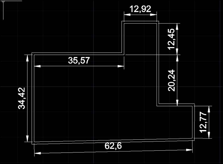
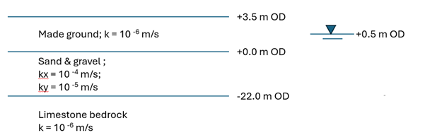
I am trying to model an excavation of 8m with secant pile wall in Seep/W for calculating the discharge for dewatering requirements. The secant pile wall is of 900mm dia hard piles. The dig level is -4.5 m OD, ground level is +3.5m OD and the water level maintained at 1.0m from the dig level (i.e. -5.5 m OD). The existing ground wate table is at +0.5m OD. The secant pile wall length is 15m from GL. The total plan area within the pile wall = 1895.63 sq. m and total perimeter = 217.5 m. The plan of the building basement is erratic see the plan layout below:
Ground Condition:
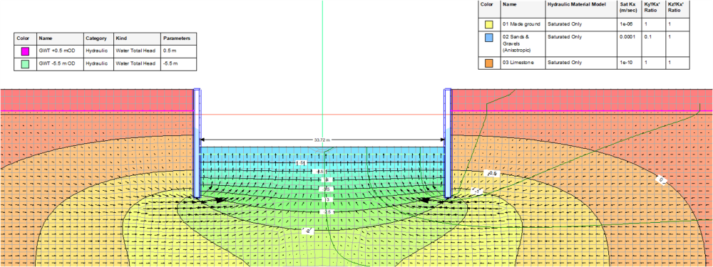
As 2D section:
I have modelled this as 2D section with average width of 33.72m and multiplied the total discharge by approx. length of 58.89m (i.e. total area / avg width).
The sand & gravel layer (blue colour) is modelled as anisotropic kx = 10-4 m/s & ky = 10-5m/s.
The total flow from the dig level = 760.68 m3/day
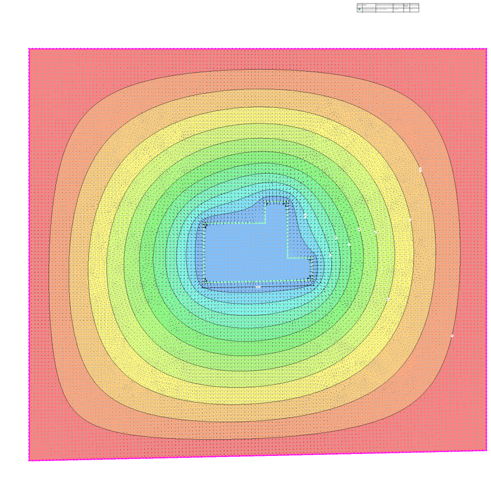
As 2D Plan:
Same plan layout is modelled as 2D plan with soil having isotropic k e = sqrt (kx * ky) = 3.16 x 10⁻⁵ m/s and measured the flow at the inner boundary of the plan. The boundary condition applied to the far boundary as +0.5m hydraulic head all around. The inner boundary is applied with -5.5m hydraulic head.
The thickness of the mesh is adopted as 10.5m (i.e.3.5m made ground layer + 22m thick sand & gravel layer – 15m secant pile wall length = the thickness of sand & gravel layer below the secant pile wall)
The total discharge = 537.8 m3/day
Please share your view on modelling this more realistically in 2D. I really appreciate your time and consideration.
Thank you.