Guidance on modelling excavation dewatering in Seep/W 2D


Hello Everyone,
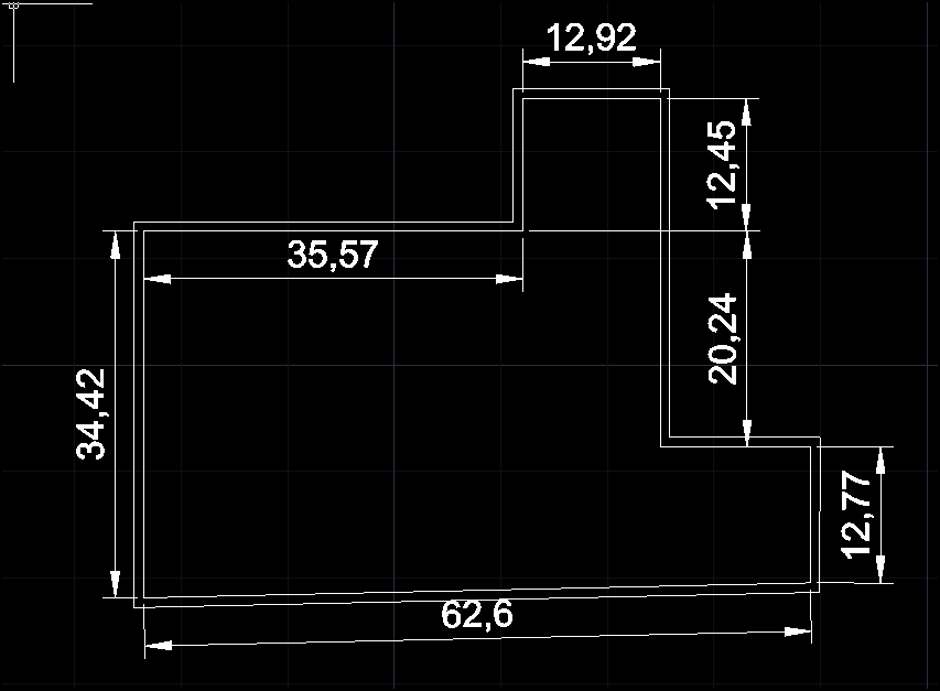
I am trying to model an excavation of 8m with secant pile wall in Seep/W for calculating the discharge for dewatering requirements. The secant pile wall is of 900mm dia hard piles. The dig level is -4.5 m OD, ground level is +3.5m OD and the water level maintained at 1.0m from the dig level (i.e. -5.5 m OD). The existing ground wate table is at +0.5m OD. The secant pile wall length is 15m from GL. The total plan area within the pile wall = 1895.63 sq. m and total perimeter = 217.5 m. The plan of the building basement is erratic see the plan layout below:
Ground Condition:
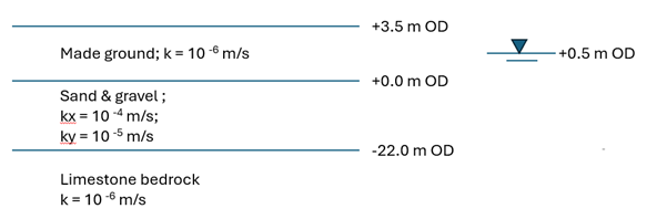
As 2D section:
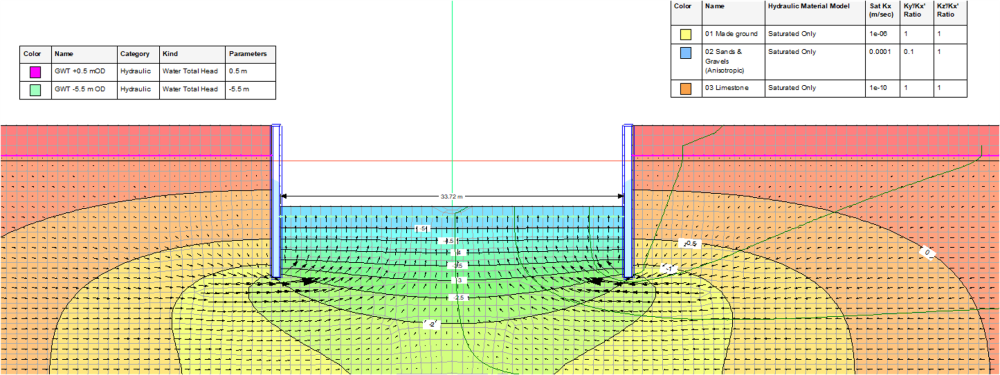
I have modelled this as 2D section with average width of 33.72m and multiplied the total discharge by approx. length of 58.89m (i.e. total area / avg width).
The sand & gravel layer (blue colour) is modelled as anisotropic kx = 10-4 m/s & ky = 10-5m/s.
The total flow from the dig level = 760.68 m3/day
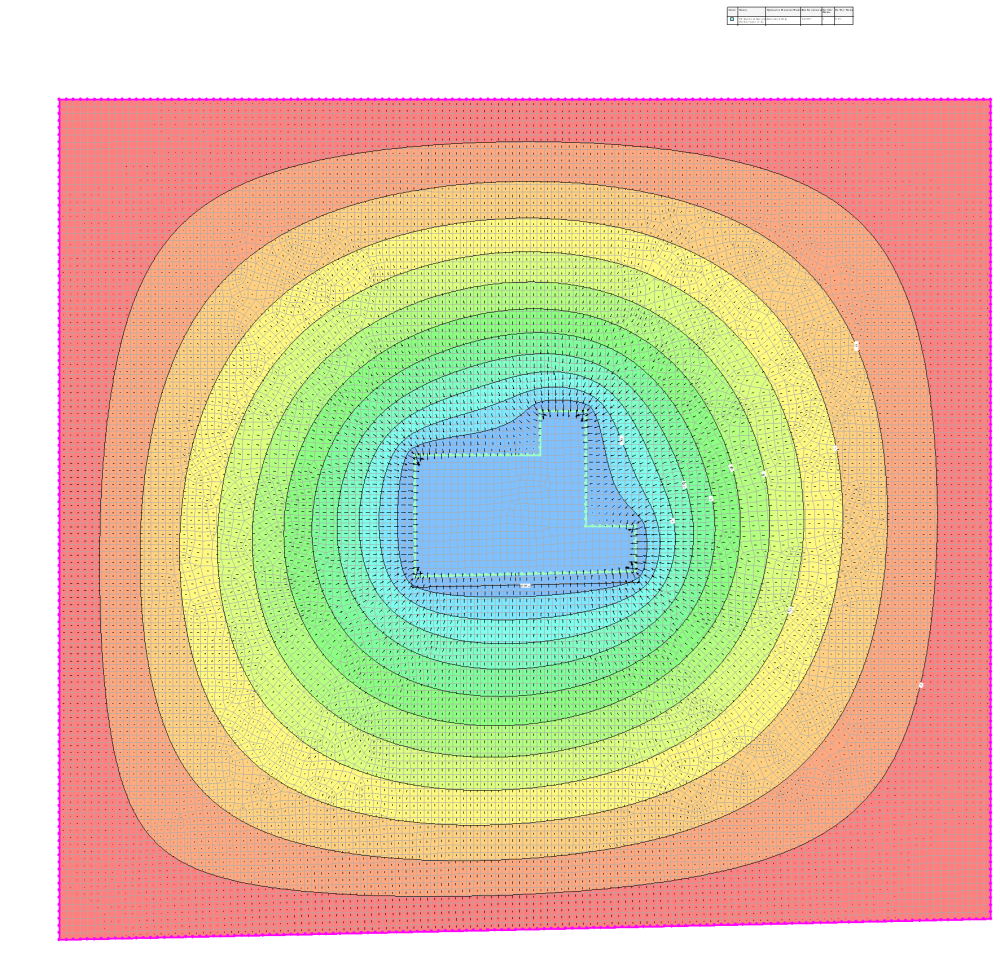
As 2D Plan:
Same plan layout is modelled as 2D plan with soil having isotropic k e = sqrt (kx * ky) = 3.16 x 10⁻⁵ m/s and measured the flow at the inner boundary of the plan. The boundary condition applied to the far boundary as +0.5m hydraulic head all around. The inner boundary is applied with -5.5m hydraulic head.
The thickness of the mesh is adopted as 10.5m (i.e.3.5m made ground layer + 22m thick sand & gravel layer – 15m secant pile wall length = the thickness of sand & gravel layer below the secant pile wall)
The total discharge = 537.8 m3/day
Please share your view on modelling this more realistically in 2D. I really appreciate your time and consideration.
Thank you.
Best Answer
-
A few items about your 2D section:
- In a seepage analysis, you want to define boundary conditions where water is entering or exiting your domain, not where it exists in the middle of your domain. These boundary condition locations are usually, but not always, along the edge of your domain. Then you verify the seepage analysis by checking how the modeled pore pressures match up with those measured in the field.
- Use the saturated/unsaturated material model to capture unsaturated flow since the water table isn't at the ground surface. Currently you're only modeling saturated flow.
- A 2D plan view analysis is for lateral flow only in a single unit - since there are multiple units plus the excavation, I don't think it is fit for purpose.
This is truly a 3D problem. You can somewhat estimate flow with a 2D section, but the assumption is that the excavation is continuous in the z-direction (out of the screen) and it doesn't capture any flow in that direction. You also can't model any dewatering well spacing in the z-direction since any boundary condition is assumed to be continuous.
Here's a SEEP3D webinar that covers some of these concepts: Mastering SEEP3D: Groundwater Flow in Shaft and Tunnel Design
2


Answers
-
Thank you !!
0