How I can adjust the projected contact surface


Hello good people!
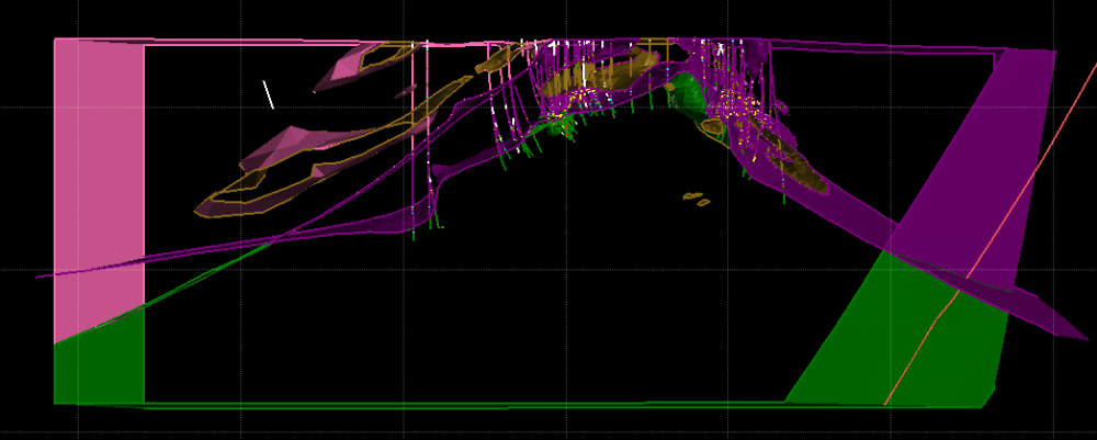
I'm trying to model an anticline here and my lower contact (purple/green) truncates into my upper contact (purple/pink) resulting the purple unit pinched out at the cross over.
But as you can see here the thickness of the purple unit is fairly consistent from the drilling, so I presume the lower contact should roughly follow the upper one.
after a few attempts I've figured that I can't apply a global trend, or it would mess up my fold limb on the right.
I can't apply a bedding structural trend, as both units are modelled as deposit.
The only successful way of adjusting it so far is by create new structural data along the contact, but it feels like explicitly manipulating the data.
Can I seek for some wisdom of why the upper and lower contact behave in such different way and if there is a less intrusive way to solve this issue? Can I influence where the projected contact would go implicitly?
Many thanks!
Newbie Geo Xiao
Best Answer
-
Hi @XiaochenXu. From the section view you are showing, the main reason the lower contact is running into the upper contact on the left hand of the view is because the selections in the last 3 drill holes are forcing the geometry into an S shape and the implicit model is simply projecting the surface out along the last known trend. This is a fundamental feature of any interpolation method once you get away from constraining data.
It does look like there is an erroneous selection of the underlying green unit in one of those drillholes that's pulling the contact into an odd bulge and creating that S shape, so I would look at that to start with. If that's all valid, then I don't see many other alternatives that don't include the creation of some explicit contact points away from the data to force the geometry to fit your interpretation. Personally I don't think it's a bad thing - you want your model to reflect your interpretation, which isn't necessarily what the implicit model wants to create.
If you do get one contact that you're happy with (say the lower contact) then the other contact can be modelled as an Offset Surface, which gives the opportunity to make a parallel shape that is locally controlled by contact points. For example, if you believe the purple unit is a roughly constant thickness then the Offset Surface would be able to make an upper contact on the right hand fold limb where I assume the drilling isn't including the overlying unit.
cheers
james
2

Answers
-
Thank you, James! These are some handy tips.
1