Distortion in point grid projected onto an inclined wireframe

Hi everyone,
I’m trying to generate a regularly spaced point grid (e.g. 40x20 m) over an inclined wireframe in Leapfrog Geo.
I first created a regular XY grid and then stamped the Z values according to the surface. However, when doing this, the grid becomes distorted, since the real spacing between points changes due to the surface inclination.
Does anyone know a way to generate a regular grid directly on the surface, keeping the spacing constant along the wireframe plane?
Or perhaps a method to correct the distortion after projecting the points in Z?
I believe that having an option to rotate the dip of point grids would solve this kind of situation — and it could also be very helpful for other use cases, such as defining drill impact grids.
Any suggestions or workarounds are very welcome!
Thanks,
Lucas Silva
Answers
-
I’m not sure if this is exactly what you’re looking for, and it may not be the most optimized workflow. I’m just sharing a workaround based on what I understand:
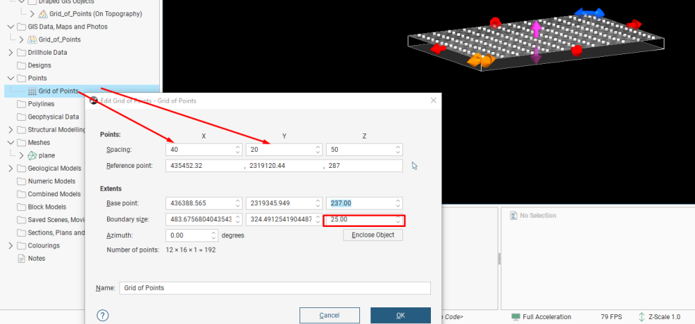
1. Create a regular point grid
- To create a grid of points, right-click on the Points folder and select “New Grid of Points” (see image below).
- Set X = 40, Y = 20, Z = 25.
- Click OK to create the grid.
2 Export the point grid
From the newly created Grid of Points folder, export the grid to your desktop.

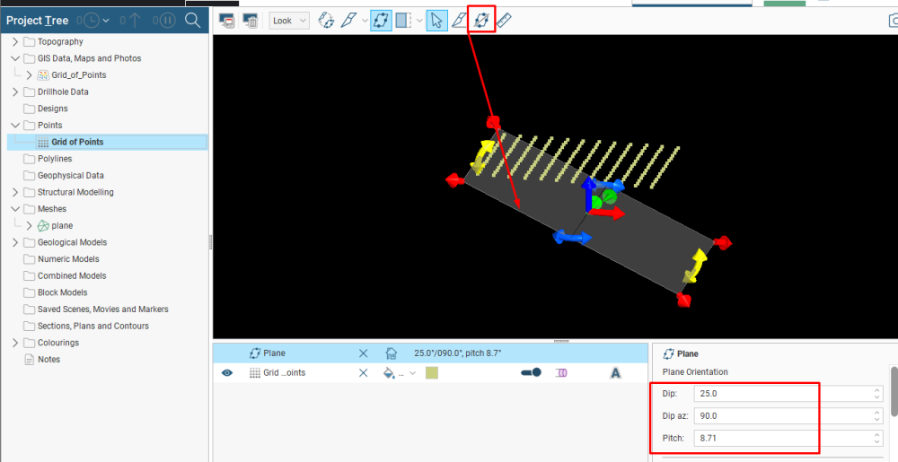
3. Create a reference plane
- Press Ctrl + 3 to open the 3D view.
- Draw a Flow Plane aligned with your wireframe surface.
- Set the Dip and Azimuth according to your project.

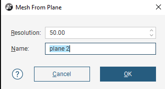
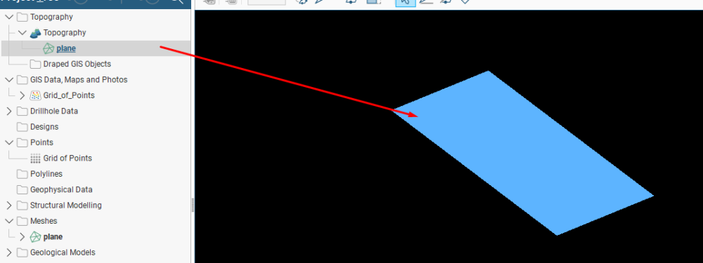
4. Create a mesh from the plane
- In Meshes folder.Right-click and choose “From Moving Plane”.
- Set the resolution to 50 and click OK.
- A blue plane should appear in your scene.

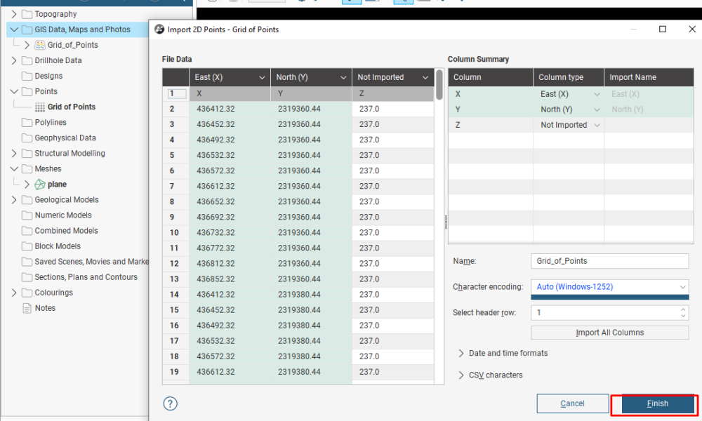
5. Import the grid points back into Leapfrog
- In the GIS data / Maps and Photos folder, right-click and select Import 2D Points.
- Select the file you exported earlier and click Open, then Finish.


6.Create a topography from the plane
In the Topography folder, right-click and select New Topography > From Surface, then choose the plane you just created from the Meshes folder.
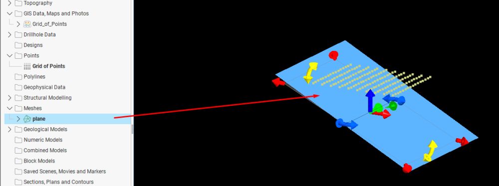
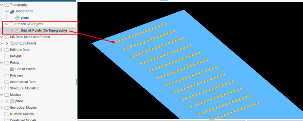
7. Project the point grid onto the inclined plane
- Go back to the GIS data / Maps and Photos folder.
- Right-click on “Grid_of_Points” and select Topography.
- Choose the topography you just created.
- You’ll now have a regular grid of points with the dimensions you set, projected onto an inclined plane.I hope this workaround is helpful for your situation.
 1
1 -
Thanks @PhamVietThai :) kind of you to share your idea on a workaround. @LucasdaSilva was that helpful?
0 -
Thanks a lot for the detailed workaround — it’s a smart approach and definitely helps in many situations.
However, there are a few caveats I’ve noticed when applying this method in projects that already have an existing topography:
- It’s not possible to create a new topography directly from a mesh when one is already defined in the project.
- In such cases, the alternative is to use the “Set Elevation” option to project the points onto the surface of the generated mesh.
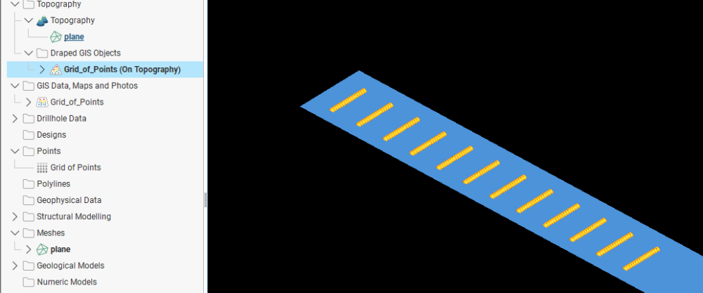
The problem, however, is that when the points are moved only in the Z direction, a distortion in real spacing occurs — since the XY distances remain fixed while elevation changes.
For planar surfaces, this can be corrected using a trigonometric adjustment based on the dip of the plane:
by slightly modifying the XY spacing when creating the grid, you can ensure that, after projection, the final spacing along the inclined surface matches the desired regular mesh.But for irregular meshes, where dip and azimuth vary continuously, this correction is not feasible — there’s no single trigonometric relationship that can preserve regular spacing everywhere.
That’s why I believe the most practical solution would be to have an option to generate a regularly spaced point grid directly on an irregular surface, preserving the true spacing along the mesh itself.
1

