💬 Ask a Geology Expert: AMA with Carly Thorpe (May 25–29)

We’re excited to host a special Ask Me Anything (AMA) with Carly Thorpe, Senior Technical Lead – Geology at Seequent, running from May 25 to May 29.
If you’ve ever had questions around workflows, modelling, or real-world challenges in mining and exploration - this is a great opportunity to ask and learn from an expert.
Topics Carly can help with:
- Mine geology
- Exploration
- Drillhole planning
- Geological modelling
- Estimation
- Leapfrog & Central workflows
How it works:
- Drop your question in the comments below ahead of time (one question per comment works best)
- Carly will review questions and start answering from May 25
- Throughout the week, responses will be shared as grouped answers, covering a few questions at a time
Whether you’re troubleshooting something specific or just curious how others approach similar challenges - feel free to jump in.
Looking forward to your questions in the comments below this thread!

Comments
-
Dear All,
I would appreciate your advice regarding an issue I am encountering during geological modeling in Leapfrog.
I first created a broader geological model using the deposit option to model the main lithological units, including soil, combined sand, primary kaolin, and debris. Following this, I created a more detailed geological model within the combined sand unit using the vein option to model internal lithologies, including sandy loam, clay, silicate horizon, secondary kaolin, and sand top.
To constrain the second model spatially, I used the combined sand volume from the first model as the lateral extent. However, when applying this restriction, the modeling process fails and returns the following error:
“Volume cutter error: The cutting mesh failed to completely cut the volume or contains holes or bad triangles. [error_tag=incomplete-cut, context=VeinBlock.VolumeCutter]”
I have checked the inputs and geometry as much as possible on my side, but I would appreciate any advice on what may be causing this issue or how best to resolve it.
Kind regards,
Oktay
 3
3 -
Hi Carly,
Question about how I could roll out Mx deposit for a new mine geology department. Any resources for understanding the capabilities and how it works for entering and managing muck, chip/channel, and test hole data. What kind of data viewing interface and reporting options are available? Another thing would be the integration of a large set of legacy data.
Cheers,
Carey
2 -
Hi @OktayErten1
CSG errors can be difficult to diagnose especially in refined models. Here are some tips on trouble shooting:
- Ensure that the volume being used as a lateral extent is closed and valid, if using an open surface ensure that the surface extends to the larger bounding box of the secondary model.
- From the error message select the option to add error locations. This can help identify where input data (drillholes, points, polylines) can be causing conflict in the surface generation.
- Turn Adaptive resolution on or off (i.e. whichever one it currently isn't).
- Adjusting the resolution of the secondary model so that it is slightly smaller than the global model can also help.
- Change the Snap to data option (or increase the Maximum snap distance if it's enabled) in the model's General tab.
You could also consider using a refined model instead of having separate GMs, these are well described in this help article:
2 -
Translation:
Hi Carly, I’m trying to model a granitic batholith with a core of unaltered granite and a weathered aureole of decomposed granite. The granite is intruding into slates and is overlain by Quaternary sediments. I can’t manage to model the batholith and the weathered aureole properly, despite trying several approaches following the available tutorials. What would you suggest?
2 -
Hi Carly, Is there a way to create a vein model using the assay datasets (by not using the numerical modelling option) from a legacy drilling files? Appreciate if you can provide a workflow or procedures please. Thanks.
Arby
2 -
Thank you so much @CarlyThorpe1 for the response. Much appreciated!
1 -
Hi Carly,
I am currently working with different types of samples within a highly dense dataset and a complex vein system, and I would like to know if there are plans to enable filtering by hole type (e.g., drillholes vs. production channels). This would allow filtering of midpoints and HW/FW contacts, helping to refine surface references and making it faster and easier to distinguish between different sample types.
Thank you,
Michelle
2 -
Hi @MartaMora
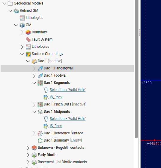
For zoned intrusions I like to use Refined Models for this type of scenario. I would first model the full volume of the granitic batholith and the Quaternary sediments. Then refine the batholith unit to separate the weathered and unweathered portion as shown in the example below.
 1
1 -
You can certainly create veins using your assay data in a Geological Model instead of Numeric Model. To do this you will first need to convert the assay data into categorical data using either Category Column From Numeric Data and then Selecting Intervals or the Economic Composites function. Once your data is in categories you can then build your veins with the vein surfaces and vein system tools in a geological model as if it were logged lithology units.
2 -
I find the best way to filter based on hole type or sample type is to use Query filters. The Standard Query Builder works well for filtering drillholes and can be applied to the dataset when selecting it for modelling your surfaces. If you have point data there is a slightly different Points Query Builder that can be used.
Some datasets don't have an appropriate field (i.e. hole type) to use for filtering; in this case you can always add a categorical selection to the collar table prior to creating the query filter to manually select the holes to use (see Categorising Points).
0 -
Hi @CareyNelson
The Seequent Learning Centre now has self-learning modules dedicated to MX Deposit including:
Configuration and Set Up in MX Deposit
If you would like to discuss licence configuration and onboarding options, please reach out to sales@seequent.com and we can connect you with your local representatives.
0 -
Thank you for your response. I apologize for not explaining myself clearly in my previous question. What I meant to ask is if there are any plans to enable filtering by a second level category (e.g., Hole_Type) at the Vein HW/FW Segments and Vein Segments Midpoints editing level within the vein construction.
Thank you,
Michelle
2 -
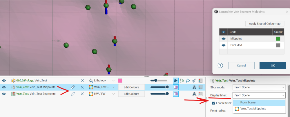
Thanks for the additional context. In LF 2026.1.1 you can apply query filter to the vein segment object in the project tree. The query filter will affect all three of the child objects (Vein midpoints, HW segments and FW segments). Query filters work independently of any edits made by manual selection and the display filter, so you have multiple levels of control on the points and segments that go into the vein.
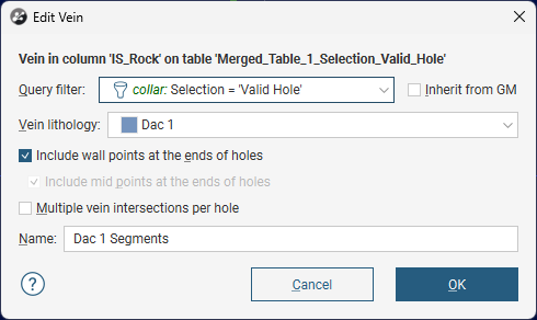
 1
1 -
G'day Carly,
hope you're loving life at Seequent.
I had a question regarding self intersecting meshes at the output volume stage of a vein-system model.
In instances where output volumes generated from chronology-based cutting contain openings, but no invalid mesh is produced (i.e. no mesh with the invalid mesh symbol
 appears, meaning there are no mesh parts available to extract and inspect), is there a way to force the creation of an invalid output volume so the affected triangles can be identified? If not, what would be the best way to identify the drilling interval (e.g. potential misallocations or flipped FW/HW segments) or polyline etc. that may be causing the chronology issue?
Extracting mesh parts from the veins prior to the chronology cutting step would not help, as all of the source vein meshes are already closed, consistent, and manifold before the chronology operation is applied.

Second question completely unrelated to geology- are there plans in future to giving the Leapfrog Geo project tree and shape list a dark-mode theme?
Thanks in advance and have a great Friday!
Darcy.
1 -
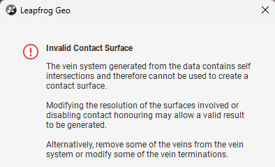
Hi @DarcyJames
There are a few things that you can try to resolve the invalid contact surface error.
- If the individual veins are closed and valid the issue may be due to misalignment of the resolution. You can try using non adaptive resolution and ensuring that all the veins that interact with each other have the same resolution.
- Often the issue is related to the complexity of the cross-cutting relationships so identifying which termination/cross over is causing the issue can be done by progressively turning these on/off.
You are not the first to request Dark Mode version of Leapfrog so I will add your name to the feature request,🌑
Thanks Carly
1 -
How do I plan ddh in leapfrog?
0